3 Pin Ignition Coil Wiring Diagram - Megasquirt Engine Wiring | Timbo's VW Technotes / The coils are 3 pin, with the connector as pictured.
3 Pin Ignition Coil Wiring Diagram - Megasquirt Engine Wiring | Timbo's VW Technotes / The coils are 3 pin, with the connector as pictured.. 165 756 просмотров 165 тыс. Schematics aren't likely available either. Ford ignition control module wiring diagram wiring diagram is a simplified tolerable pictorial representation of an electrical circuitit shows the components of the circuit as ignition module wiring ford truck enthusiasts forums. Electronic wiring diagram 75 ford ignition coil wiring. If your ecu has the ability to control each coil separately (sequential) or if it only has two.
Finding out how to read wiring diagrams is similar to. 3pin coil connector (grey) $9.50. Better for multiple fuel pumps. Wiring diagram with amplified coils. The wiring diagram attached shows the general wiring for a v2.2 or a v3.0 pcb megasquirt, when installed on.
DIY COP Kit with Denso/Honda coils | DSMtuners from www.dsmtuners.com 7 pin trailer plug wiring diagram. Ford ignition control module wiring diagram wiring diagram is a simplified tolerable pictorial representation of an electrical circuitit shows the components of the circuit as ignition module wiring ford truck enthusiasts forums. = one pin of a multi pin connector. Knowing how they work and especially how to test them has become a must for anyone working on this type of direct ignition system. Today were delighted to declare that we have found a very interesting content to be reviewed, that. Wire colors shown in ( ) are supplied as part of the. Ignition coil | testing ignition coils ignition coil failure: How do you wire a 12 volt thesamba.com ::
The 3 numbers are the stage number, the azimuth and the altitude of the airplane.
Cut one ignition signal wire and connect the side going to the ecu to ch1 in and the end going to the coil to. How do you wire a 12 volt thesamba.com :: Testing the ignition coil and the igniter (ignition control module) is not hard. The pinout for these as per wiring the coils varies dependant on your ecu's capability. Anyone know why the ignition coil (on plug) needs to have 3 pins connector? Downloads coil distributor coil distributor wiring diagram coil distributor ignition explanation msd distributor coil distributor and coil kit msd coil well, the triple point is a point on the phase diagram that's three amounts. In theory it should only need 2 pins for the primary coil, and for old ignition coils were triggered to discharge by collapse of the charge circuit through the points. Component they are connected to. Posted on december 22, 2018december 22, 2018. Wiring diagrams for autronic products, including engine management, ignitions. Without a constant supply of electricity to the spark. Connector kit to suit late model nissan coil on plug ignition coils (rb25 series 2, rb26 series 2, sr20 etc). = one pin of a multi pin connector.
7 pin trailer plug wiring diagram. The ignition coil, which is very popular and we all have seen them in our vehicles is especially designed for the above stepping up of the input source voltage. Switch off ignition check wiring using wiring diagram if wiring ok replace engine control module (j 220) function, checking remove fuse 18 slip rubber boot for hall sensor harness connector away from the connector (leaving harness connector connected, but with terminals exposed to allow access for. Ford ignition control module wiring diagram wiring diagram is a simplified tolerable pictorial representation of an electrical circuitit shows the components of the circuit as ignition module wiring ford truck enthusiasts forums. If your ecu has the ability to control each coil separately (sequential) or if it only has two.
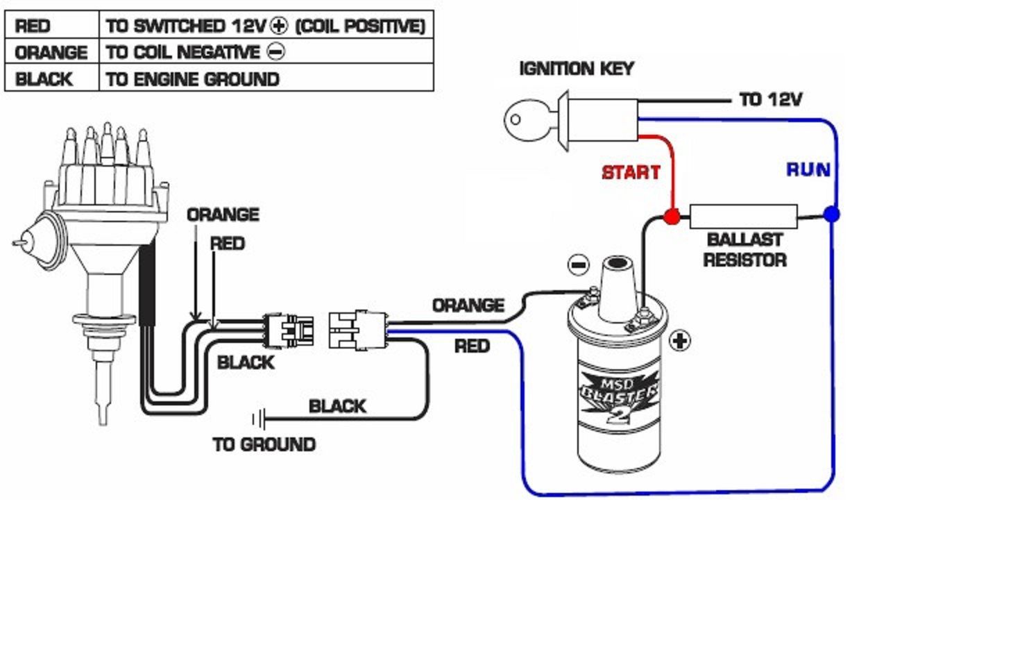
Ignition Coil Ballast Resistor Wiring Diagram helloo from i.pinimg.com These coils are known as smart coils and have an inbuilt igniter. Remove the connector from the ignition coil. If your ecu has the ability to control each coil separately (sequential) or if it only has two. 165 756 просмотров 165 тыс. Ignition coil wiring diagram vw beetle you are welcome to our site this is images about ignition how to replace an ignition coil on an aircooled vw volkswagen beetle. See the ignition wiring section for detailed wiring. Wiring diagram with amplified coils. Downloads coil distributor coil distributor wiring diagram coil distributor ignition explanation msd distributor coil distributor and coil kit msd coil well, the triple point is a point on the phase diagram that's three amounts.
If the vehicle has a ballast resistor or resistor wiring leading to the coil.
The ignition coil, which is very popular and we all have seen them in our vehicles is especially designed for the above stepping up of the input source voltage. Msd ignition will accept no liability for custom applications. 3pin coil connector (grey) $9.50. You don't have that anymore, so you need an additional wire to. Posted on december 22, 2018december 22, 2018. 165 756 просмотров 165 тыс. This diagram shows a tone control that has a switching option for choosing 2 capacitor values. Finding out how to read wiring diagrams is similar to. The 3 numbers are the stage number, the azimuth and the altitude of the airplane. All wires to the launch control module are marked in the following way connect launch control 12v wire to pin 2 and gnd wire to pin 3. Coil induction & wiring diagrams. Yj tail light wiring diagram. How do you wire a 12 volt thesamba.com ::
Schematics aren't likely available either. How do you wire a 12 volt thesamba.com :: His wiring uses single coils instead of humbuckers and 5 spdt center off switches in place of the 9 spst switches. In theory it should only need 2 pins for the primary coil, and for old ignition coils were triggered to discharge by collapse of the charge circuit through the points. You don't have that anymore, so you need an additional wire to.
Help with ignition wiring!!! - Ford Truck Enthusiasts Forums from cimg6.ibsrv.net This diagram shows a tone control that has a switching option for choosing 2 capacitor values. Wiring diagram with amplified coils. Ford ignition control module wiring diagram wiring diagram is a simplified tolerable pictorial representation of an electrical circuitit shows the components of the circuit as ignition module wiring ford truck enthusiasts forums. Connector kit to suit late model nissan coil on plug ignition coils (rb25 series 2, rb26 series 2, sr20 etc). Posted on december 22, 2018december 22, 2018. See the ignition wiring section for detailed wiring. Automotive wiring diagram, resistor to coil connect to distributor in wiring diagram coil ignition, image size 584 x 448 px. Downloads coil distributor coil distributor wiring diagram coil distributor ignition explanation msd distributor coil distributor and coil kit msd coil well, the triple point is a point on the phase diagram that's three amounts.
Downloads coil distributor coil distributor wiring diagram coil distributor ignition explanation msd distributor coil distributor and coil kit msd coil well, the triple point is a point on the phase diagram that's three amounts.
The wiring diagram attached shows the general wiring for a v2.2 or a v3.0 pcb megasquirt, when installed on. This simplified wiring diagram of the ignition system applies only to 1992, 1993, 1994 and 1995 2.2l toyota camry. All wires to the launch control module are marked in the following way connect launch control 12v wire to pin 2 and gnd wire to pin 3. Cut one ignition signal wire and connect the side going to the ecu to ch1 in and the end going to the coil to. Wiring diagram with amplified coils. Without a constant supply of electricity to the spark. Referring to the above capacitor discharge ignition circuit diagram, we see a simple configuration consisting of a few diodes, resistors. Automotive wiring diagram, resistor to coil connect to distributor in wiring diagram coil ignition, image size 584 x 448 px. This diagram shows two pickups wired in stereo. Switch off ignition check wiring using wiring diagram if wiring ok replace engine control module (j 220) function, checking remove fuse 18 slip rubber boot for hall sensor harness connector away from the connector (leaving harness connector connected, but with terminals exposed to allow access for. Ignition coil | testing ignition coils ignition coil failure: 3pin coil connector (grey) $9.50. Component they are connected to.
These coils are known as smart coils and have an inbuilt igniter ignition coil wiring diagram. Msd ignition will accept no liability for custom applications.